Gladius III Design & Validation
This fall, MARC’s president Nikolas and Structures team lead Pierce joined me in reaching out to engineers at Second Order Effects. They had contacted MARC during my freshman year about reviewing our designs to help us improve upon Gladius I, which was a huge help as we developed Gladius II. Nikolas, Pierce, and I created a semi-formal design report highlighting the steps that Structures has taken to respond to Gladius II’s failed launch, from structural redesigns to the selection of a motor with a similar net impulse but lower, safer thrust.
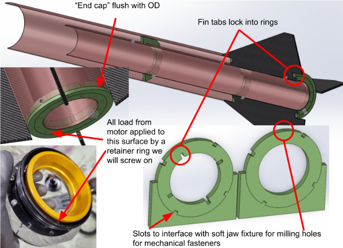
I’ve been spearheading our complete revamp of the centering rings, which connect the motor tube to the aft airframe body, and other structural components such as the bulkheads that provide internal barriers between Gladius III’s components, which I’ve taught new members how to optimize for maximum hole separation by utilizing SolidWorks’ sketch relations. Some of our key changes are highlighted below, such as my teammate Max’s idea for partially embedding the fins into the centering rings to add further redundancy for preventing them from ripping out. I brainstormed a way of creating screw holes on the centering rings so that they can be held in place at more locations than only using epoxy would allow, and developed a completely new approach to assembling the aft airframe. This time, we’ll slide the entire pre-assembled compound of centering rings, fins, and the motor tube into the rocket body, dramatically increasing internal contact for both load transfer and epoxy bonding surface area.
I’ve also conducted preliminary SolidWorks finite element analysis (FEA) tests to verify that these redesigned structural components can better withstand the expected 2 kN peak motor thrust, which is something we’ll be hearing back from Second Order Effects on shortly. This process has involved a lot of CAD work and configuration, including manually editing SolidWorks material properties at the code level.

