Frame Construction
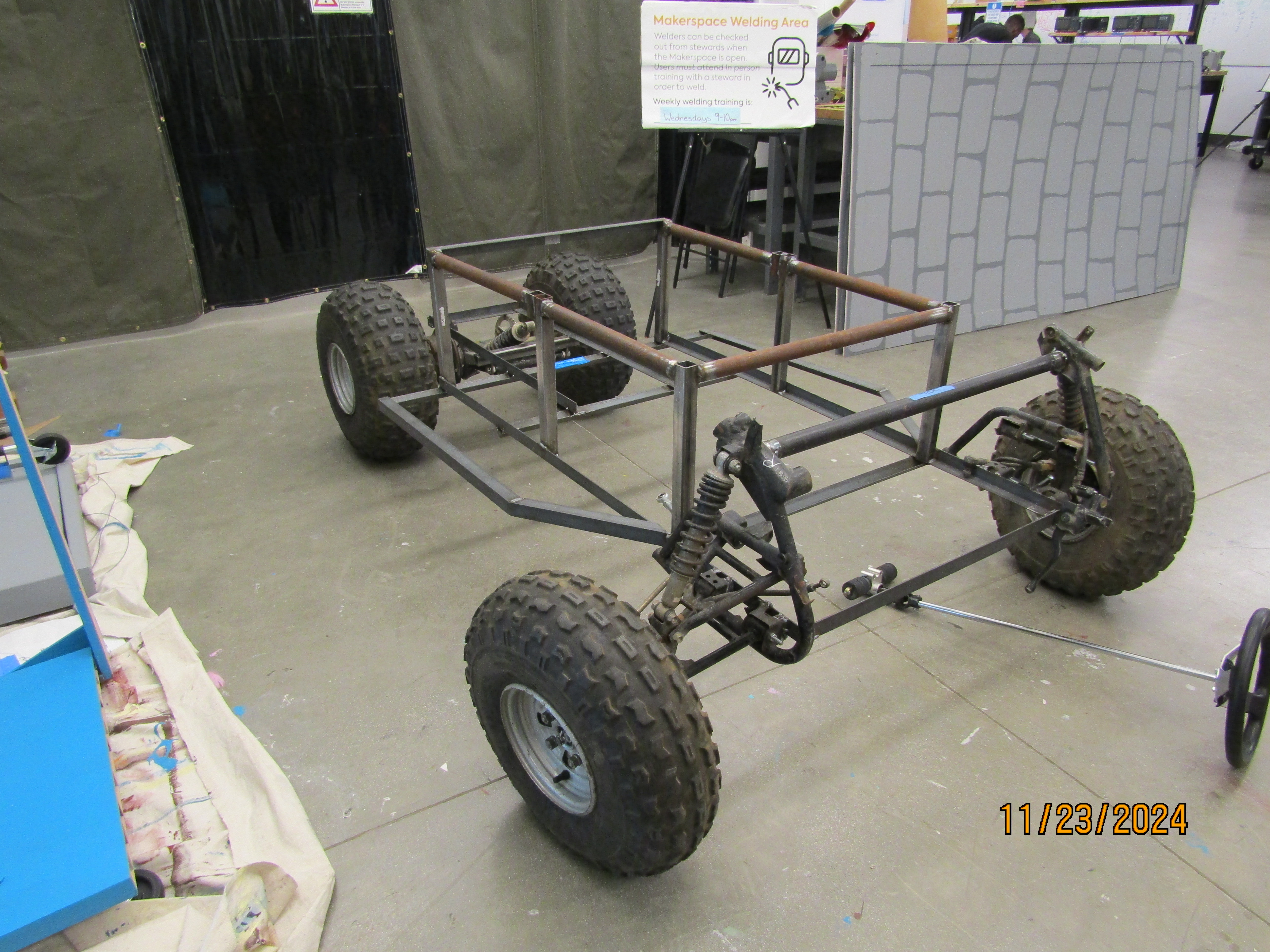
Here and there over the course of two semesters, as we’ve purchased angle iron and steel tubing, MACH has put together the vast majority of our go-kart’s structural frame. Our next steps are to mount the rear axle, then figure out how to rig the steering and where and how to mount the electric motor and ICE motor.

Learning how to MIG weld to build the frame has been a blast! I’m no expert by any means, but it’s rewarding to see how my weld quality has improved over just a handful of sessions. Below is a clip of one of my earlier welds, from before we were donated ATV parts, when we were still anticipating using a mini go-kart rear axle kit. It’s also been fun to relearn as well as teach new members how to use some of the equipment in the Mudd Makerspace and Machine Shop to get the frame components to size before welding them.
Many members have been instrumental in frame design and assembly; for example, Lily frequently creates sketches that help us visualize the three-dimensionality of the go-kart and its various sections, and Josaphat helped translate our frame into CAD. Befoer that, our work began very humbly with sketching out the frame on butcher paper.


Although the general frame shape is something that we’ve played by ear, once the base layer was assembled we moved on to more deliberately determining where and how to attach vertical components to stiffen the frame and interface with the front and rear wheels, especially once we realized we had to make changes to fit the ginormous ATV wheels we now have.

To that end, for example, Felipe took measurements of the rear axle, and then from there I attempted to calculate the relative spacing between its two mounting points, designing with the goal of having the shock tower vertically oriented when not under load. These calculations helped constrain the design space of the entire rear frame and transmission area of the go-kart, which is something we initially didn’t know where to begin, although they need to be modified to account for the fact that we’re designing the go-kart to be “stinkbugged” (in which the frame sinks below the horizontal, from the rear to the front).

