Custom Remote-Control Rover & Parachute
During the descent phase of the launch, FAR teams can deploy an autonomous or remote-control rover to perform reconnaissance tasks (i.e. capturing footage as it returns to the launch site, independently from the rocket). Our team began by deconstructing a Team Associated MT28 RC car. Previous team lead Allison integrated the PCBs for our camera, and built a transistor arrangement that deactivates an electromagnet as soon as the rover starts driving, to detach its parachute mount, a steel disk I cut via lathe and embedded into a 3D-printed plate, upon touching down. This would allow the rover to shed the mass and drag of the parachute as we drove it back to the launch site.
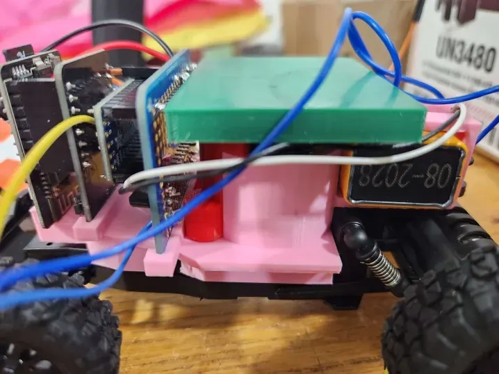

Over several iterations, I designed and printed the mounting plate that interfaces with all of these components, including screw mounts that clamp down the electromagnet and the mounting plate itself, simultaneously. One constraint I kept in mind as I created the mount’s CAD was ensuring that the electromagnet was positioned roughly near the center of mass of the final assembly, to ensure that the rover body would be roughly flat upon touchdown, taking full advantage of its suspension to minimize the risk of damage.


At one point, we attempted to modify an existing all-terrain rover, which uses helical wheels. After experimenting with someone’s prototype of that rover, and determining that even with TPU filament, the helical wheels just couldn’t get traction on concrete or dirt or sand or rocks, we found that further modifying the rover and downscaling it to fit in the rocket was no longer worth pursuing.


A major subchallenge for designing the rover was figuring out how to create the parachute it would connect to. With my teammates Anthony and Sebastian, after calculating the area needed for a maximum landing speed of 2.5 m/s, I built and tested two versions of a custom parachute cut from a massive polyethylene sheet, which would attach to the parachute mount via plastic cords.

